EN
EN
What is Aluminum Profile and How Does It Work?
2026/09/30
Source aluminum profiles for versatile modular framing. Learn extrusion mechanics, strength benefits & corrosion resistance. Request details.

2026/09/11
Calculating load capacity for an aluminum profile is essential when designing structural systems, machine frames, or industrial equipment. An aluminum profile must support its intended weight without deflection, buckling, or failure. Understanding the fundamental principles of load calculation ensures your industrial aluminum components perform reliably under real-world conditions. This process combines material properties, cross-sectional geometry, and load distribution analysis into a practical engineering framework.
The load-carrying capacity of aluminum extrusion profiles depends on multiple interconnected factors. Material grade, cross-sectional shape, moment of inertia, support conditions, and environmental stresses all influence how much load a profile can safely handle. Engineers and designers must evaluate these variables systematically to determine safe working loads and prevent structural failure. Proper calculation protects equipment longevity, worker safety, and operational efficiency across manufacturing, automation, and infrastructure sectors.
The yield strength of aluminum extrusion material defines the stress level at which permanent deformation begins. Common aluminum alloys used in industrial aluminum components include 6061-T6, 6063-T5, and 7075-T73, each with different strength ratings. A 6061-T6 aluminum profile typically yields around 40,000 PSI, while 7075-T73 extrusion reaches approximately 73,000 PSI. Knowing your material grade is the first step in calculating maximum safe load capacity. Material certifications and supplier documentation must always specify the exact alloy and temper designation.
Engineers apply a safety factor to account for manufacturing tolerances, environmental variables, and uncertainty in loading conditions. A typical safety factor for static aluminum profile applications ranges from 1.5 to 3.0, depending on application criticality and load predictability. The allowable stress is calculated by dividing the yield strength by the applied safety factor. For example, if a 6061-T6 aluminum extrusion has 40,000 PSI yield strength and a safety factor of 2.0, the allowable working stress is 20,000 PSI. This conservative approach prevents unexpected structural failures in industrial aluminum components and aluminum structural framing systems.
The moment of inertia (I) measures how resistant an aluminum profile cross-section is to bending around an axis. Thicker walls and larger overall dimensions increase moment of inertia, allowing the extrusion to support greater loads without deflection. For rectangular aluminum structural framing, moment of inertia is calculated using the formula I = (b × h³) / 12 minus any hollow sections. Manufacturers provide moment of inertia data in their technical specifications for standard aluminum extrusion profiles. This value is critical for determining deflection limits and maximum bending stresses under load conditions.
Section modulus (S) is derived from moment of inertia and is used directly in bending stress calculations for aluminum profile design. The bending stress formula is Stress = Bending Moment / Section Modulus. When a load is applied to an industrial aluminum component or aluminum structural framing member, it creates internal bending moments. By comparing calculated bending stress against the allowable stress (yield strength divided by safety factor), engineers determine whether the aluminum extrusion can safely handle the applied load. Higher section modulus values indicate greater load-carrying capacity relative to weight, making certain aluminum profile geometries more efficient for specific applications.
Aluminum profiles in industrial aluminum components experience different load types depending on the application. A point load concentrates force at a single location, while distributed loads spread across the entire length of the aluminum extrusion. Cantilever loading (force applied to one end while the profile is fixed at the opposite end) produces maximum stress near the fixed point. Simply supported loading (profile resting on two supports with load applied between them) distributes stress differently. Each load scenario produces different bending moments and requires specific calculation approaches to verify safe load capacity.
The standard workflow for calculating load capacity begins with defining the load scenario and aluminum profile geometry. Step one identifies the material grade and yield strength from supplier documentation. Step two calculates moment of inertia from cross-sectional dimensions or retrieves this value from aluminum extrusion technical data sheets. Step three applies the appropriate safety factor to determine allowable stress levels. Step four calculates the maximum bending moment that can develop under the anticipated load pattern. Step five compares actual stresses against allowable limits to confirm safe operation. Many engineers use load capacity calculators or FEA software for complex aluminum profile configurations, but manual calculations using fundamental formulas remain valuable for verification and understanding load behavior in industrial aluminum components and aluminum structural framing systems.
Static load calculations assume constant, unchanging forces applied to the aluminum extrusion. However, real industrial aluminum components frequently experience cyclic or impact loading that reduces safe load capacity below static limits. Vibration, thermal expansion, and repeated loading cycles can cause fatigue failure at stress levels well below the material yield strength. Aluminum profile design for machinery automation must account for fatigue life requirements and environmental stresses. Temperature changes affect material properties and can introduce additional internal stresses in aluminum structural framing systems. Corrosive environments may accelerate material degradation and reduce long-term load capacity.
Buckling represents a critical failure mode for slender aluminum profiles under compression or combined bending-compression loading. Column buckling capacity depends on profile geometry, material properties, length, and end-support conditions. An aluminum extrusion with fixed ends at both ends resists buckling much more effectively than a profile with pinned or free ends. Slenderness ratio (length divided by the least radius of gyration) directly influences buckling resistance. Engineers must verify both bending stress and buckling safety when designing tall or slender aluminum profile structures. Industrial aluminum components used as columns or vertical supports require careful analysis to prevent sudden catastrophic failure, especially in load-bearing aluminum structural framing applications where personnel safety depends on structural integrity.
Yield strength and material temper are the most critical properties. The specific aluminum alloy designation (such as 6061-T6 or 7075-T73) must be verified from supplier documentation. Additionally, the modulus of elasticity (Young's modulus) affects deflection behavior. Cross-sectional dimensions and moment of inertia determine how efficiently the aluminum extrusion resists bending. All these properties work together to establish safe load capacity for your industrial aluminum components and aluminum structural framing applications.
Apply a safety factor by dividing the material yield strength by a multiplier typically ranging from 1.5 to 3.0, depending on application type and criticality. The resulting allowable stress is then used to calculate maximum safe loads for your aluminum profile design. Safety factors compensate for manufacturing variations, environmental uncertainties, and unpredictable loading patterns. Building safety margins into calculations prevents unexpected failures and extends the service life of aluminum structural framing and industrial aluminum components in real-world conditions.
Yes, many manufacturers provide load calculators specifically designed for their aluminum extrusion profiles and aluminum structural framing products. Finite Element Analysis (FEA) software offers advanced modeling capabilities for complex aluminum component configurations. However, understanding fundamental calculation methods remains important for verification and confidence in results. Starting with manual calculations using basic formulas helps validate software outputs and ensures you recognize load capacity limitations before deployment of industrial aluminum components in production environments.
2026/09/30
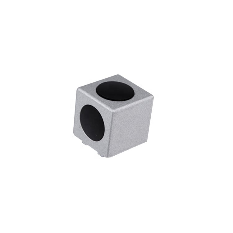
Source aluminum profiles for versatile modular framing. Learn extrusion mechanics, strength benefits & corrosion resistance. Request details.
2026/09/30
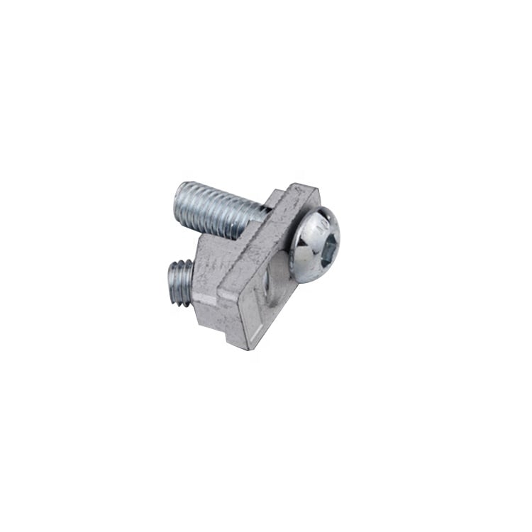
Source aluminum profiles for construction projects. Learn structural framing, cladding & window benefits for maximum ROI. Download guide.
2026/09/30
Source optimal aluminum profile sizing techniques. Evaluate load, space, alloy, environment & cost factors to prevent deflection. Download guide.
2026/09/30
Struggling with fastener failures or rework? Master screw sizing by diameter, pitch, material, and load—plus industry-specific standards. Optimize reliability & compliance now.
2026/09/30
Source aluminum profiles for industrial engineering. Discover strength-to-weight ratios, corrosion resistance & 30% cost savings. Download guide.
2026/09/30
Source heat-resistant aluminum profile systems. Master thermal expansion science & stress management strategies for industrial builds. Download guide.