EN
EN
What is Aluminum Profile and How Does It Work?
2026/09/30
Source aluminum profiles for versatile modular framing. Learn extrusion mechanics, strength benefits & corrosion resistance. Request details.

2026/09/08
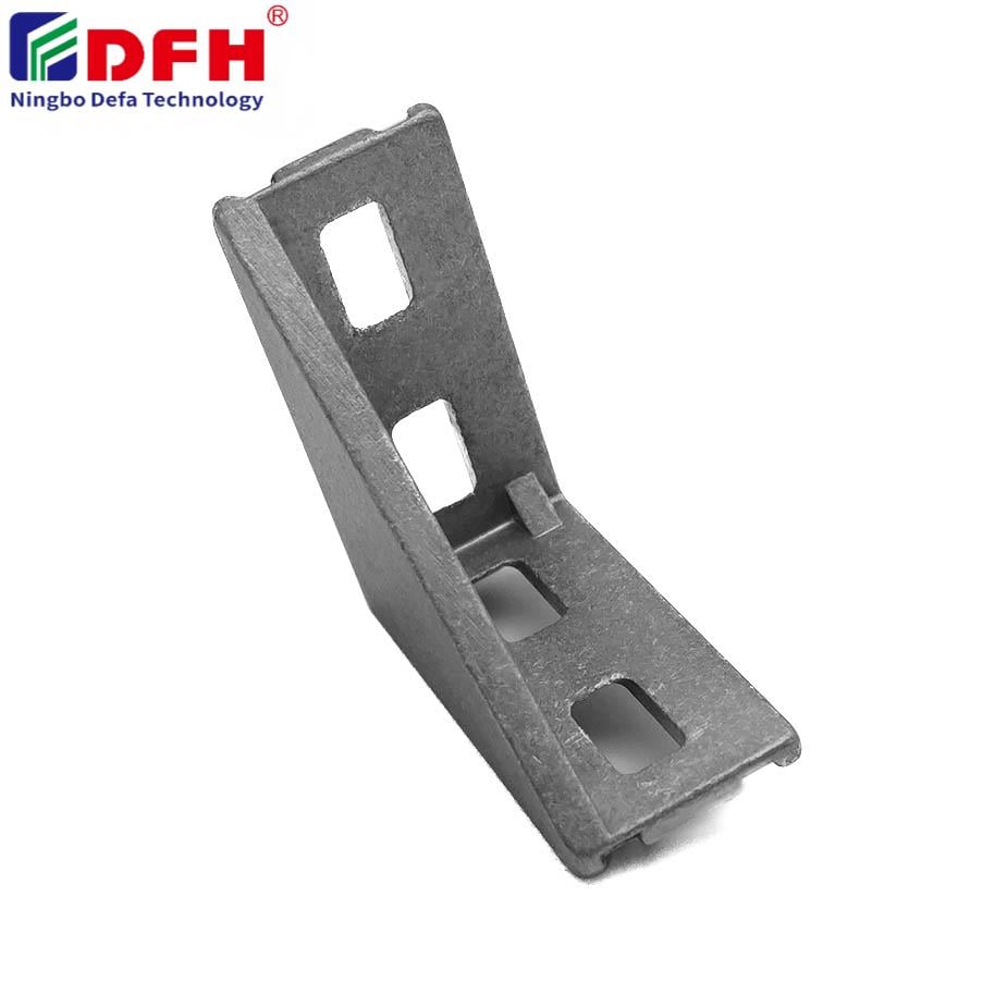
Proper installation of End Connectors is essential for ensuring reliable electrical connections, mechanical integrity, and long-term performance in industrial applications. Whether you're working with automation equipment, control systems, or complex wiring assemblies, the way you install end connectors directly impacts system reliability and safety. Improper installation can lead to intermittent failures, corrosion, poor signal transmission, and costly downtime. This guide walks you through the correct installation methods, tools, and best practices to achieve professional-grade results every time.
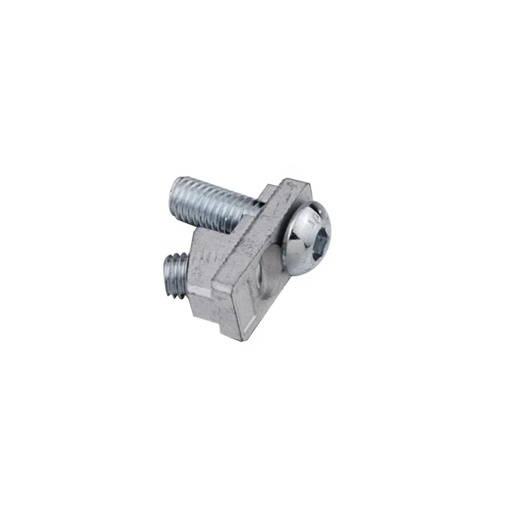
Understanding the correct installation process for connector terminals and connection hardware begins with recognizing that each connector type has specific requirements based on its design, material composition, and intended use. Cable end connectors vary in pin configuration, contact pressure, sealing mechanisms, and environmental protection ratings. The installation procedure must account for these variations to prevent damage to delicate contacts, ensure proper mating force, and maintain environmental seals that protect against moisture, dust, and contaminants.
Before beginning any installation work, thoroughly inspect your end connectors, cable assemblies, and mating surfaces. Check for visible damage, corrosion, bent pins, or contamination on connector terminals. Verify that the cable gauge matches the connector specifications and that insulation is intact without cuts or abrasion. Inspect the receptacle or mating connector to ensure contacts are clean, properly aligned, and free from debris. Any pre-existing damage compromises the quality of the final connection and can introduce failure points that are difficult to diagnose later.
Proper installation of cable end connectors requires appropriate tools: wire strippers sized to your cable diameter, crimping tools calibrated for your specific connector terminals, ferrule applicators if applicable, and torque wrenches for threaded connection hardware. Organize your work area with static-dissipative surfaces if working with sensitive electronic equipment. Have contact cleaning agents, protective caps, and anti-oxidant compounds available. Using the wrong tools—particularly undersized or miscalibrated crimpers—causes incomplete contact seating, poor electrical continuity, and accelerated corrosion that compromises connection performance over time.
Strip the cable insulation to the exact length specified in the connector datasheet, typically between 6 and 10 millimeters depending on connector type. Measure carefully to avoid removing too much insulation, which exposes bare copper to the environment and increases contamination risk. Remove too little insulation and the wire will not seat properly in the connector terminal, creating a weak mechanical and electrical joint. After stripping, twist multi-strand conductors tightly together and ensure no individual strands protrude beyond the primary bundle. Stray strands can cause shorts, reduce contact pressure, and compromise the reliability of your connection hardware.
For applications requiring enhanced corrosion resistance, apply a thin layer of anti-oxidant compound or contact grease to the stripped conductor before inserting it into the connector terminal. This protective layer prevents oxidation at the contact interface, maintains electrical conductivity over extended periods, and reduces the likelihood of corrosion-induced failures. Insert the stripped conductor into the terminal socket smoothly and completely, ensuring it seats against the internal contact spring without forcing. The wire should slide in with minimal resistance; if excessive force is required, the terminal may be damaged or misaligned, resulting in poor contact quality and potential open circuits.
Position the connector terminal and wire in your crimping tool, ensuring the terminal is centered in the crimp nest. Apply steady, even pressure as you close the crimper, listening and feeling for the characteristic 'click' that indicates proper crimp completion. Most quality crimpers have a ratcheting mechanism that prevents removal until adequate pressure has been applied. The crimped connection should show visible indentation marks without crushing the terminal housing or severing the wire strands. Inspect the crimped joint—the wire and terminal should form a unified mechanical and electrical connection that resists pulling apart with moderate manual force. Under-crimped connections separate easily and cause intermittent failures, while over-crimped joints damage terminal material and degrade contact surfaces.
After crimping all connector terminals, visually inspect each joint for proper seating, symmetrical crimp marks, and absence of damage. Gently pull on each wire to verify the crimp holds without slipping. Check that the overall connector assembly has no loose components, cracked housings, or improperly seated terminals. If your application uses connector backshells or strain relief components, install these according to manufacturer specifications to protect the cable and connection hardware from mechanical stress, bending fatigue, and environmental exposure. Properly installed backshells distribute stress loads and extend connector service life significantly.
Use a digital multimeter to verify electrical continuity across each connection. Measure resistance between the wire conductor and the mating contact to confirm conductivity, which should read near zero ohms for solid connections. Resistance readings above 1 ohm suggest marginal contact quality, incomplete crimping, or oxidation. For multi-pin assemblies, test pin-to-pin isolation to verify that no unintended shorts exist between adjacent connector terminals. These measurements provide quantitative assurance that your cable end connectors meet electrical performance requirements before deployment. Catching marginal connections during testing prevents failures in the field that would require expensive troubleshooting and system downtime.
Once testing confirms proper connection, apply protective caps to unmated connectors to prevent accidental damage, dust accumulation, and corrosion. For outdoor or harsh environments, consider additional sealing measures such as conformal coatings or protective sleeves over connection hardware. Label each assembly with reference numbers, pin assignments, and installation date for maintenance tracking. Document the connector type, wire gauge, crimp tool used, and any relevant torque specifications. This documentation aids future troubleshooting, supports maintenance planning, and ensures consistency if replacement connectors are needed. Proper records also satisfy compliance requirements in regulated industries where traceability and installation verification are mandatory.
The most frequent error is under-crimping, which occurs when inadequate pressure is applied during the crimping process. Under-crimped connector terminals do not grip the wire securely, allowing it to slip under vibration, thermal cycling, or mechanical stress. This creates intermittent electrical failures that are difficult to diagnose because the connection appears correct visually but fails under operational conditions. Using a properly calibrated crimping tool with a ratcheting mechanism largely prevents this problem by ensuring consistent, repeatable crimp quality across all cable end connectors.
Temperature, humidity, salt spray, and chemical exposure all influence connection reliability and longevity. Installation in humid or corrosive environments requires anti-oxidant compounds, sealed connector terminals, and protective backshells to prevent premature corrosion. Cold temperatures can make certain materials brittle, affecting crimp quality, while thermal cycling induces expansion and contraction that stresses connection hardware. Installation procedures should account for the final operating environment by selecting appropriate materials, applying protective coatings, and using sealing components rated for the expected conditions. These preventive measures during installation eliminate the majority of field failures related to environmental degradation.
Connector terminals should be replaced if they show visible damage, bent contacts, cracks, deformation during crimping, or signs of corrosion. Attempting to reuse damaged connector terminals results in unreliable connections, poor contact quality, and hidden failure mechanisms. Each installation cycle stresses the terminal material, and reused terminals have reduced contact pressure and mechanical integrity. For critical applications and regulated environments, manufacturers recommend using new connector terminals for each installation to ensure consistent performance and maintain compliance with quality standards. This practice eliminates variables and guarantees that connection hardware meets design specifications.
2026/09/30
Source aluminum profiles for versatile modular framing. Learn extrusion mechanics, strength benefits & corrosion resistance. Request details.
2026/09/30
Source aluminum profiles for construction projects. Learn structural framing, cladding & window benefits for maximum ROI. Download guide.
2026/09/30
Source optimal aluminum profile sizing techniques. Evaluate load, space, alloy, environment & cost factors to prevent deflection. Download guide.
2026/09/30
Struggling with fastener failures or rework? Master screw sizing by diameter, pitch, material, and load—plus industry-specific standards. Optimize reliability & compliance now.
2026/09/30
Source aluminum profiles for industrial engineering. Discover strength-to-weight ratios, corrosion resistance & 30% cost savings. Download guide.
2026/09/30
Source heat-resistant aluminum profile systems. Master thermal expansion science & stress management strategies for industrial builds. Download guide.